- 您现在的位置:买卖IC网 > Sheet目录356 > SI8402AB-B-IS (Silicon Laboratories Inc)IC I2C ISOLATOR BIDIR 8-SOIC
Si840x
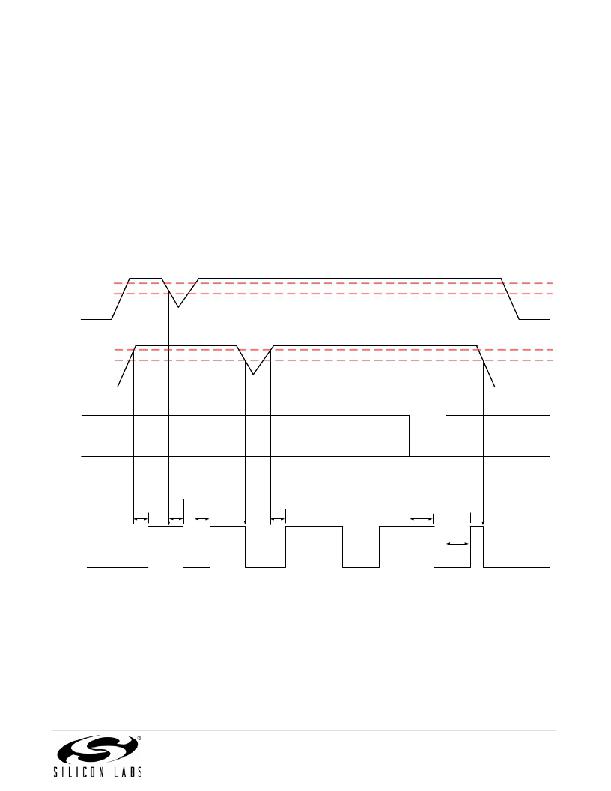
3. Device Operation
Device behavior during start-up, normal operation, and shutdown is shown in Figure 7, where UVLO+ and UVLO–
are the positive-going and negative-going thresholds respectively. Refer to Table 12 to determine outputs when
power supply (VDD) is not present.
3.1. Device Startup
Outputs are held low during powerup until VDD is above the UVLO threshold for time period tSTART. Following
this, the outputs follow the states of inputs.
3.2. Under Voltage Lockout
Under Voltage Lockout (UVLO) is provided to prevent erroneous operation during device startup and shutdown or
when VDD is below its specified operating circuits range. Both Side A and Side B each have their own under
voltage lockout monitors. Each side can enter or exit UVLO independently. For example, Side A unconditionally
enters UVLO when AVDD falls below AVDD UVLO– and exits UVLO when AVDD rises above AVDD UVLO+ . Side B
operates the same as Side A with respect to its BVDD supply.
UVLO+
UVLO-
AVDD
UVLO+
UVLO-
BVDD
INPUT
tSTART
tSD
tSTART
tSTART
tPH L
tPLH
OUTPUT
Figure 7. Device Behavior during Normal Operation
Rev. 1.6
13
发布紧急采购,3分钟左右您将得到回复。
相关PDF资料
SI8405AB-A-IS1
IC ISOLATOR 10M 6CH 2.5K 16SOIC
SI8423BD-B-IS
ISOLATOR 2CH 5KV 150M 16SOIC
SI8435BB-C-IS1
IC ISOLATOR DGTL 3CH 16SOIC
SI8442BB-C-IS1
IC ISOLATOR DGTL 4CH 16SOIC
SI8451BB-A-IS1
IC ISOLATOR DGTL 5CH 16SOIC
SI8460BB-A-IS1
IC ISOLATOR DGTL 6CH 16SOIC
SI8606AC-B-IS1
IC ISOLATOR BIDIR 3.75KV 16SOIC
SI8621ED-B-IS
IC ISOLATOR 2CH 5KV 16-SOIC
相关代理商/技术参数
SI8402AB-B-ISR
制造商:Silicon Laboratories Inc 功能描述:2.5 KV BIDIRECTIONAL I2C ISOLATOR, UNI CLK, 1.7MHZ, SOIC8, L - Tape and Reel 制造商:Silicon Laboratories Inc 功能描述:IC I2C ISOLATOR BIDIR 8-SOIC 制造商:Silicon Laboratories Inc 功能描述:2.5 KV BIDIRECTIONAL I2C ISOLATOR 1.7MHz
SI8402DB
制造商:VISHAY 制造商全称:Vishay Siliconix 功能描述:20-V N-Channel 1.8-V (G-S) MOSFET
SI8402DB_06
制造商:VISHAY 制造商全称:Vishay Siliconix 功能描述:20-V N-Channel 1.8-V (G-S) MOSFET
SI8402DB_08
制造商:VISHAY 制造商全称:Vishay Siliconix 功能描述:20-V N-Channel 1.8-V (G-S) MOSFET
SI8402DB-T1
制造商:VISHAY 制造商全称:Vishay Siliconix 功能描述:20-V N-Channel 1.8-V (G-S) MOSFET
SI8402DB-T1-E1
功能描述:MOSFET 20V 6.8A RoHS:否 制造商:STMicroelectronics 晶体管极性:N-Channel 汲极/源极击穿电压:650 V 闸/源击穿电压:25 V 漏极连续电流:130 A 电阻汲极/源极 RDS(导通):0.014 Ohms 配置:Single 最大工作温度: 安装风格:Through Hole 封装 / 箱体:Max247 封装:Tube
SI8402DB-T1-E3
制造商:Vishay Semiconductors 功能描述:
SI-8402L
制造商:SANKEN 制造商全称:Sanken electric 功能描述:Separate Excitation Switching Type with Coil
